 EN
EN
 AR
AR
 BG
BG
 HR
HR
 CS
CS
 DA
DA
 NL
NL
 FI
FI
 FR
FR
 DE
DE
 EL
EL
 HI
HI
 IT
IT
 JA
JA
 KO
KO
 NO
NO
 PL
PL
 PT
PT
 RO
RO
 RU
RU
 ES
ES
 SV
SV
 TL
TL
 VI
VI
 TH
TH
 TR
TR
 GA
GA
 CY
CY
 BE
BE
 IS
IS
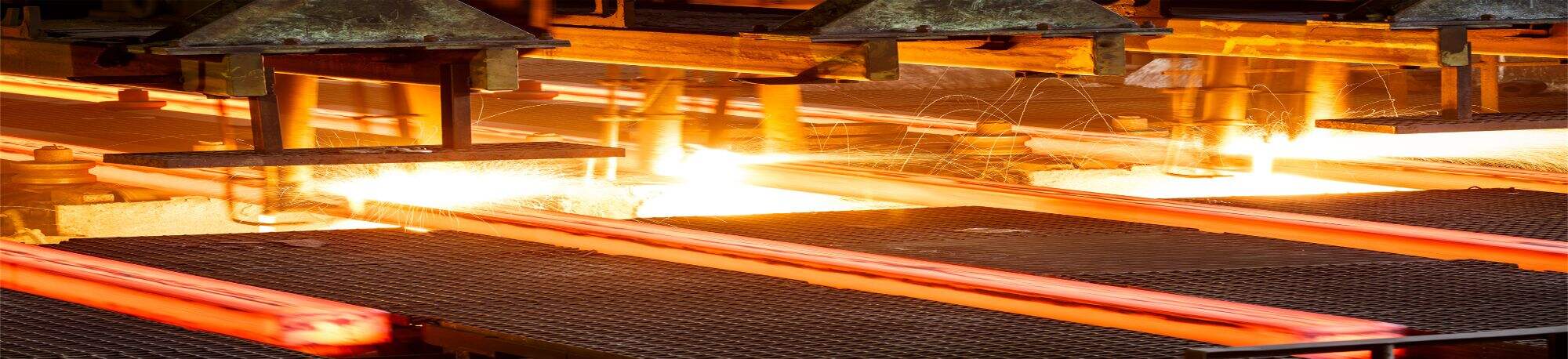
Stainless Steel for Semiconductor & Pharma UPW Systems: How Micro-Surface Finish Impacts Product Yield
Stainless Steel for Semiconductor & Pharma UPW Systems: How Micro-Surface Finish Impacts Product Yield
In semiconductor fabrication and pharmaceutical manufacturing, Ultra-Pure Water (UPW) is the lifeblood of production. Contamination at parts-per-billion (ppb) or even parts-per-trillion (ppt) levels can cripple product yield. While water treatment processes are critical, the materials transporting UPW—typically stainless steel—play an equally vital role. The micro-surface finish of stainless steel components directly dictates contamination risk, biofilm formation, and ultimately, product yield. Here’s a detailed analysis of why surface finish matters and how to optimize it.
? 1. Why Surface Finish is Non-Negotiable in UPW Systems
UPW must meet extraordinary purity standards:
-
Semiconductors: Resistivity ≥18.2 MΩ·cm, total organic carbon (TOC) <1 ppb.
-
Pharma: Compliance with USP <643> and EP <2.2.29> guidelines.
Rough surfaces create:
-
Bacterial adhesion sites: Even nano-scale imperfections harbor biofilms.
-
Particle shedding: Micro-peaks break off, introducing metallic contaminants.
-
Corrosion initiation: Roughness accelerates crevice corrosion, releasing ions (Fe, Cr, Ni).
? 2. Measuring Surface Finish: Ra vs. Rmax
-
Ra (Arithmetic Average Roughness): The most common metric, but insufficient for UPW. An Ra ≤0.5 µm may still hide "peak-and-valley" defects.
-
Rmax (Maximum Peak-to-Valley Height): Critical for UPW systems. Specifying Rmax ≤0.5 µm ensures no extreme outliers.
-
Electropolished Finish: The gold standard. It levels micro-peaks, enhances passive layer formation, and reduces effective surface area.
⚙️ 3. How Surface Finish Impacts Contamination
A. Bacterial Colonization
-
Rough surfaces (Ra >0.8 µm) provide protective niches for bacteria like Pseudomonas or Ralstonia, which thrive in UPW.
-
Result: Biofilms shed cells and endotoxins into water, risking wafer defects or injectable drug contamination.
B. Particulate Generation
-
Unpolished surfaces shed particles during flow turbulence.
-
In semiconductors, these particles cause wafer scratches or photolithography defects.
C. Metallic Ion Leaching
-
Microscopic crevices trap water, leading to localized corrosion and ion release (e.g., Fe³⁺, Cr⁶⁺).
-
Impact: Metal ions catalyze unwanted reactions in pharma or reduce dielectric yields in chips.
?️ 4. Achieving the Perfect Finish: Mechanical vs. Electropolishing
Mechanical Polishing
-
Process: Sequential grinding with abrasive pads (e.g., 80 to 600 grit).
-
Limitation: Smears metal surface, embedding oxides and creating "plucking" sites for future particle release.
-
Max Achievable: Ra ≈0.3 µm (good, but not ideal for UPW).
Electropolishing
-
Process: Anodic dissolution in acid bath (e.g., phosphoric-sulfuric acid) removes ~20–40 µm of surface.
-
Advantages:
-
Reduces Ra to ≤0.15 µm and Rmax to ≤0.5 µm.
-
Seals the surface with a thick, uniform chromium oxide layer.
-
Eliminates embedded contaminants and micro-cracks.
-
-
Required Standards: Follow ASTM B912 for passivation and SEMI F19 for electropolishing.
✅ 5. Material Selection: Beyond 316L
While 316L is standard, consider:
-
Low-Carbon Variants: 316L with <0.02% C prevents sensitization during welding.
-
Electropolishing-Grade (EP): Mills supply 316L-EP with tighter inclusion controls (e.g., sulfur <0.001%).
-
Alternative Alloys: For extreme applications, 904L or 6% Mo alloys (e.g., 254 SMO) offer better corrosion resistance.
? 6. Validation and Testing
Surface Profilometry
-
Use contact (stylus) or non-contact (laser) profilometers to verify Ra/Rmax.
Ferroxyl Testing
-
Detects free iron contamination—a common issue after mechanical polishing.
Water Testing
-
Monitor TOC, endotoxins, and particle counts in effluent water.
-
Acceptance Criteria: ≤5 particles/mL (for size ≥0.1 µm) and endotoxins <0.001 EU/mL.
? 7. Maintenance: Keeping Surfaces Pristine
-
Passivation: Periodic nitric or citric acid passivation per ASTM A967 to rejuvenate the chromium layer.
-
Chemical Cleaning: Avoid chloride-containing cleaners. Use ozone or hydrogen peroxide for biofilms.
-
Inspection: Regular borescope checks of pipes and tanks for rouge (iron oxide) formation.
? 8. Case Study: Surface Finish Upgrade Boosts Yield
-
Problem: A semiconductor fab experienced recurring particle defects on 7nm wafers.
-
Root Cause: UPW pipes with Ra ≈0.6 µm (mechanically polished) shed particles during flow spikes.
-
Solution: Replaced with electropolished 316L-EP (Ra ≤0.15 µm).
-
Result: Particle counts dropped by 70%, and wafer yield increased by 5%.
? 9. Key Specifications for UPW Components
| Component | Required Ra | Required Rmax | Process |
|---|---|---|---|
| Pipes & Tubes | ≤0.15 µm | ≤0.5 µm | Electropolished |
| Tanks & Vessels | ≤0.2 µm | ≤0.8 µm | Electropolished |
| Fittings & Valves | ≤0.2 µm | ≤0.8 µm | Mechanically polished + EP |
✅ 10. Conclusion: Invest in Finish, Protect Yield
In UPW systems, the difference between high yield and catastrophic failure lies in micro-scale surface topography. Electropolishing is not an expense—it’s an insurance policy. By specifying low-Ra/Rmax finishes, validating with profilometry, and maintaining rigorous cleanliness protocols, you ensure that your stainless steel infrastructure supports—not sabotages—your production goals.
Pro Tip: When sourcing components, demand certified test reports for surface roughness and insist on electropolishing from vendors audited to SEMI F19 standards.